저번 포스팅에서 EFM32 Happy Gecko Starter Kit를 사용하기 위한 기초적인 준비작업을 해보았습니다. Simplicity Studio의 데모와 소프트웨어 예제들을 이용하여 키트에 내장된 여러 센서들을 사용해볼 수 있습니다. 이번 시간에는 humitemp라는 온도를 측정하는 예제를 직접 사용해보고 예제 코드를 분석해보겠습니다.
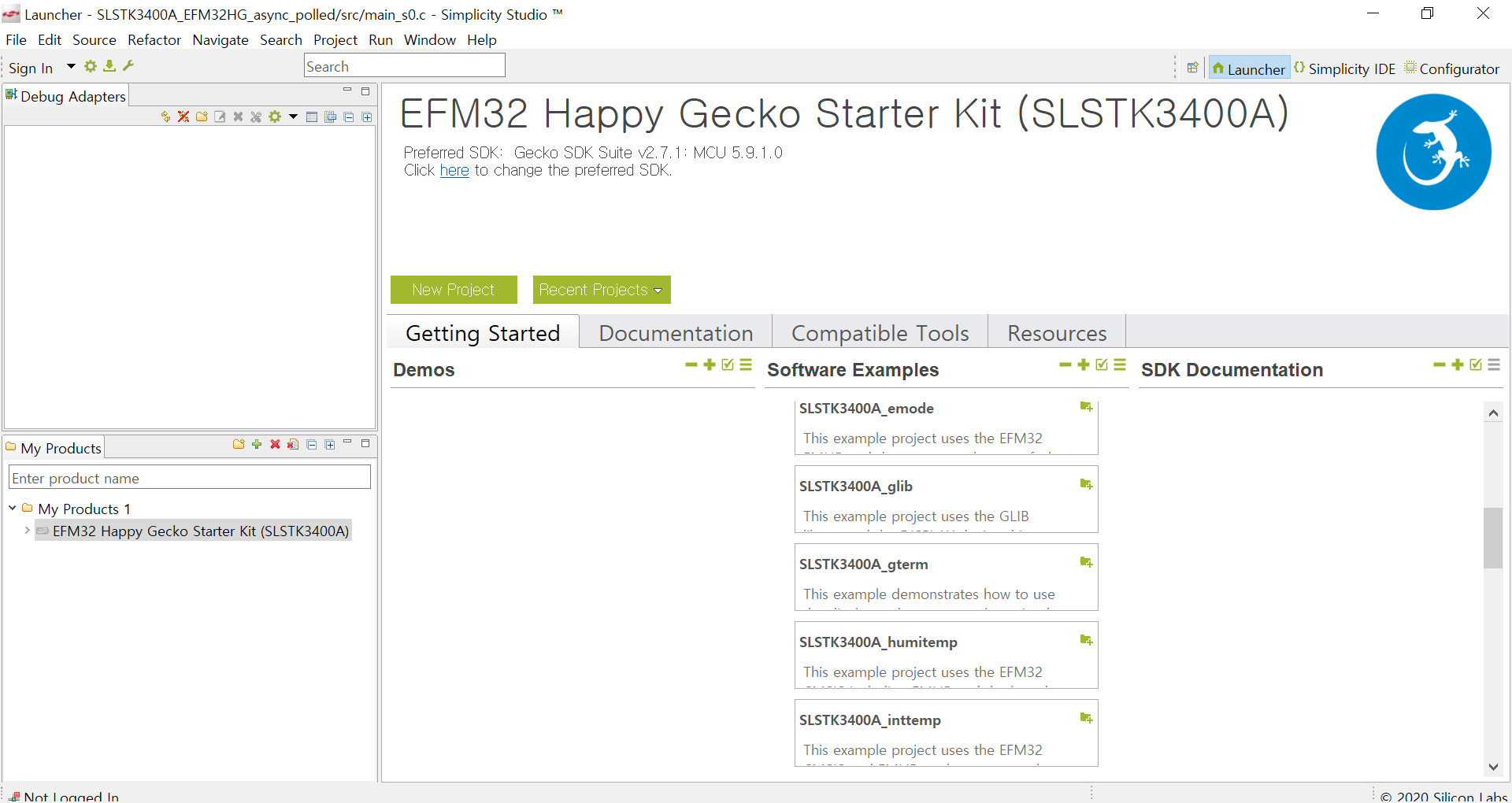
먼저 Simplicity Studio를 실행해보도록 하겠습니다. 아래의 화면에서 보이는 [Software Example]에 있는 예제 리스트들을 보면 humitemp를 찾을 수 있습니다.
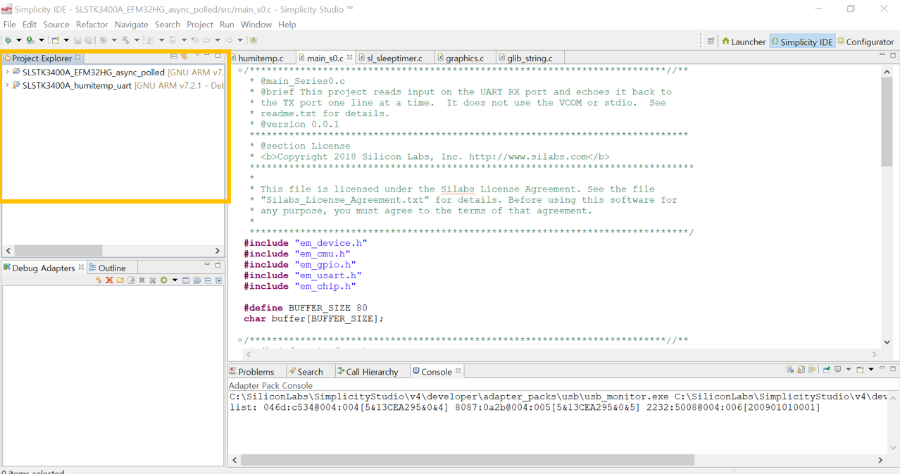
humitemp 예제를 클릭하면 Simplicity IDE로 화면이 전환이 되면서 Project Explorer에 소프트웨어 예제가 추가가 되는 것을 보실 수 있습니다. 아래의 사진에서는 제가 미리 작업해놓은 예제 프로젝트 파일들이 있습니다.
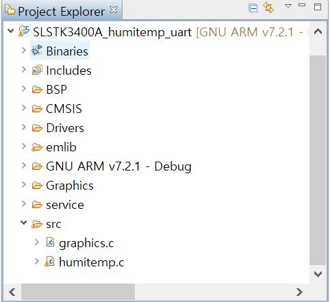
Project Explorer에 추가된 humitemp 예제의 메인 코드를 불러오기 위해서는 (위 사진은 제가 파일 이름을 수정한 것입니다.) 파일 이름 앞의 작은 화살표를 누른 뒤 src 파일로 들어가면 humitemp.c라는 파일이 있는데 이 파일을 클릭하면 됩니다. 참고로 src는 소스코드의 약자입니다. 자 이제 본격적으로 humitemp 예제를 분석해보도록 하겠습니다.
/***************************************************************************//**
 * @file
 * @brief Relative humidity and temperature sensor demo for SLSTK3400A_EFM32HG
 *******************************************************************************
 * # License
 * <b>Copyright 2018 Silicon Laboratories Inc. www.silabs.com</b>
 *******************************************************************************
 *
 * The licensor of this software is Silicon Laboratories Inc. Your use of this
 * software is governed by the terms of Silicon Labs Master Software License
 * Agreement (MSLA) available at
 * www.silabs.com/about-us/legal/master-software-license-agreement. This
 * software is distributed to you in Source Code format and is governed by the
 * sections of the MSLA applicable to Source Code.
 *
 ******************************************************************************/

#include "em_device.h"
#include "em_chip.h"
#include "em_cmu.h"
#include "em_emu.h"
#include "em_gpio.h"
#include "i2cspm.h"
#include "si7013.h"
#include "sl_sleeptimer.h"
#include "graphics.h"
#include "em_adc.h"
#include "bspconfig.h"

/***************************************************************************//**
 * Local defines
 ******************************************************************************/

/** Time (in ms) between periodic updates of the measurements. */
#define MEASUREMENT_INTERVAL_MS      2000
/** Voltage defined to indicate dead battery. */
#define LOW_BATTERY_THRESHOLD   2800

/***************************************************************************//**
 * Local variables
 ******************************************************************************/
/* Variables used by the display callback. */
static void (*mem_lcd_callback_func)(void*) = 0;
static void *mem_lcd_callback_arg = 0;

/** Flag used to indicate ADC is finished */
static volatile bool adcConversionComplete = false;

/** This flag indicates that a new measurement shall be done. */
static volatile bool measurement_flag = true;

/** Timer used for periodic update of the measurements. */
sl_sleeptimer_timer_handle_t measurement_timer;

/** Timer used for periodic maintenance of the display **/
sl_sleeptimer_timer_handle_t display_timer;

/***************************************************************************//**
 * Local prototypes
 ******************************************************************************/
static void gpioSetup(void);
static uint32_t checkBattery(void);
static void adcInit(void);
static void measure_humidity_and_temperature(I2C_TypeDef *i2c, uint32_t *rhData, int32_t *tData, uint32_t *vBat);
static void measurement_callback(sl_sleeptimer_timer_handle_t *handle, void *data);

/***************************************************************************//**
 * @brief  Main function
 ******************************************************************************/
int main(void)
{
  I2CSPM_Init_TypeDef i2cInit = I2CSPM_INIT_DEFAULT;
  uint32_t         rhData;
  bool             si7013_status;
  int32_t          tempData;
  uint32_t         vBat = 3300;
  bool             lowBatPrevious = true;
  bool             lowBat = false;

  /* Chip errata */
  CHIP_Init();

  /* Use LFXO for rtc used by the sleeptimer */
  CMU_ClockSelectSet(cmuClock_LFA, cmuSelect_LFXO);
  CMU_ClockEnable(cmuClock_HFLE, true);

  /* Initalize peripherals and drivers */
  gpioSetup();
  adcInit();
  sl_sleeptimer_init();
  GRAPHICS_Init();
  I2CSPM_Init(&i2cInit);

  /* Get initial sensor status */
  si7013_status = Si7013_Detect(i2cInit.port, SI7021_ADDR, NULL);
  GRAPHICS_ShowStatus(si7013_status, false);
  sl_sleeptimer_delay_millisecond(2000);

  /* Set up periodic measurement timer */
  sl_sleeptimer_start_periodic_timer_ms(&measurement_timer, MEASUREMENT_INTERVAL_MS, measurement_callback, NULL, 0, 0);

  EMU_EnterEM2(false);

  while (true) {
    if (measurement_flag) {
      measure_humidity_and_temperature(i2cInit.port, &rhData, &tempData, &vBat);
      measurement_flag = false;
      if (lowBatPrevious) {
        lowBat = (vBat <= LOW_BATTERY_THRESHOLD);
      } else {
        lowBat = false;
      }
      lowBatPrevious = (vBat <= LOW_BATTERY_THRESHOLD);
      GRAPHICS_Draw(tempData, rhData, lowBat);
    }
    EMU_EnterEM2(false);
  }
}

/***************************************************************************//**
 * @brief Setup GPIO interrupt for pushbuttons.
 *****************************************************************************/
static void gpioSetup(void)
{
  /* Enable GPIO clock */
  CMU_ClockEnable(cmuClock_GPIO, true);

  /* Enable si7021 sensor isolation switch */
  GPIO_PinModeSet(gpioPortC, 8, gpioModePushPull, 1);
}

/***************************************************************************//**
 * @brief This function is called whenever we want to measure the supply v.
 *        It is reponsible for starting the ADC and reading the result.
 ******************************************************************************/
static uint32_t checkBattery(void)
{
  uint32_t vData;
  /* Sample ADC */
  adcConversionComplete = false;
  ADC_Start(ADC0, adcStartSingle);
  while (!adcConversionComplete) EMU_EnterEM1();
  vData = ADC_DataSingleGet(ADC0);
  return vData;
}

/***************************************************************************//**
 * @brief ADC Interrupt handler (ADC0)
 ******************************************************************************/
void ADC0_IRQHandler(void)
{
  uint32_t flags;

  /* Clear interrupt flags */
  flags = ADC_IntGet(ADC0);
  ADC_IntClear(ADC0, flags);

  adcConversionComplete = true;
}

/***************************************************************************//**
 * @brief ADC Initialization
 ******************************************************************************/
static void adcInit(void)
{
  ADC_Init_TypeDef       init       = ADC_INIT_DEFAULT;
  ADC_InitSingle_TypeDef initSingle = ADC_INITSINGLE_DEFAULT;

  /* Enable ADC clock */
  CMU_ClockEnable(cmuClock_ADC0, true);

  /* Initiate ADC peripheral */
  ADC_Init(ADC0, &init);

  /* Setup single conversions for internal VDD/3 */
  initSingle.acqTime = adcAcqTime16;
  initSingle.input   = adcSingleInpVDDDiv3;
  ADC_InitSingle(ADC0, &initSingle);

  /* Manually set some calibration values */
  ADC0->CAL = (0x7C << _ADC_CAL_SINGLEOFFSET_SHIFT) | (0x1F << _ADC_CAL_SINGLEGAIN_SHIFT);

  /* Enable interrupt on completed conversion */
  ADC_IntEnable(ADC0, ADC_IEN_SINGLE);
  NVIC_ClearPendingIRQ(ADC0_IRQn);
  NVIC_EnableIRQ(ADC0_IRQn);
}

/***************************************************************************//**
 * @brief  Helper function to perform data measurements.
 ******************************************************************************/
static void measure_humidity_and_temperature(I2C_TypeDef *i2c, uint32_t *rhData, int32_t *tData, uint32_t *vBat)
{
  *vBat = checkBattery();
  Si7013_MeasureRHAndTemp(i2c, SI7021_ADDR, rhData, tData);
}

/***************************************************************************//**
 * @brief Callback from timer used to initiate new measurement
 ******************************************************************************/
static void measurement_callback(sl_sleeptimer_timer_handle_t *handle, void *data)
{
  (void) handle;
  (void) data;
  measurement_flag = true;
}

/***************************************************************************//**
 * @brief   The actual callback for Memory LCD toggling
 ******************************************************************************/
static void display_callback(sl_sleeptimer_timer_handle_t *handle, void *data)
{
  (void)handle;
  (void)data;
  mem_lcd_callback_func(mem_lcd_callback_arg);
}

/***************************************************************************//**
 * @brief   Register a callback function at the given frequency.
 *
 * @param[in] pFunction  Pointer to function that should be called at the
 *                       given frequency.
 * @param[in] argument   Argument to be given to the function.
 * @param[in] frequency  Frequency at which to call function at.
 *
 * @return  Always return 0
 ******************************************************************************/
int rtcIntCallbackRegister(void (*pFunction)(void*),
                           void* argument,
                           unsigned int frequency)
{
  mem_lcd_callback_func = pFunction;
  mem_lcd_callback_arg  = argument;
  uint32_t ticks = sl_sleeptimer_get_timer_frequency() / frequency;
  sl_sleeptimer_start_periodic_timer(&display_timer, ticks, display_callback, NULL, 0, 0);

  return 0;
}
예제 코드가 정말 깁니다. 처음에 예제 코드 분석 시작할 때 코드의 양만 보고 겁먹으시는 분들 많습니다. 그렇지만 코드의 핵심은 main 함수 안에 있다는 것을 명심해 주셨으면 좋겠습니다. 그럼 main 함수를 중심으로 분석을 해보도록 하겠습니다.
I2CSPM_Init_TypeDef i2cInit = I2CSPM_INIT_DEFAULT;
uint32_t rhData;
bool si7013_status;
int32_t tempData;
uint32_t vBat = 3300;
bool lowBatPrevious = true;
bool lowBat = false;
이 부분은 크게 중요한 부분들은 아니고 처음에 초깃값을 설정해 주는 부분입니다.
/* Chip errata */
CHIP_Init();
이 코드는 처음에 시작할 때 칩을 초기화해주는 부분입니다.
/* Use LFXO for rtc used by the sleeptimer */
CMU_ClockSelectSet(cmuClock_LFA, cmuSelect_LFXO);
CMU_ClockEnable(cmuClock_HFLE, true);
회로도 관련 포스팅에서 오실레이터 종류 중에 LFXO가 있다는 것을 설명해드렸습니다. 이 부분은 오실레이터의 한 종류인 LFXO를 사용하여 CMU의 클럭을 세팅하고 클럭을 사용할 수 있게 해주는 부분입니다.
/* Initalize peripherals and drivers */
여기서부터는 주변 기기 및 장치들을 초기화해주는 부분입니다.
gpioSetup();
기초적이지만 중요한 것은 핀 설정 부분입니다. 그래서 이 함수에 대해서 알아보았습니다. 참고로 함수를 찾을 때 코드에 커서를 갖다 대서 함수를 드래그를 한 뒤 키보드의 F3을 누르면 그 함수에 대한 정보가 있는 곳으로 이동하게 됩니다. 코드 분석할 때 유용한 기능이므로 꼭 기억해두시길 바랍니다. 저도 코드를 분석할 때 자주 사용합니다. 밑의 사진처럼 드래그해서 사용하시면 됩니다.
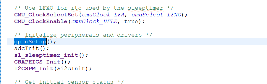
다시 본론으로 들어와서 gpioSetup() 함수에 대해 설명드리겠습니다.
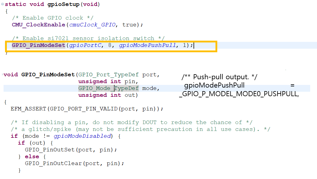
함수를 찾아서 들어가 보니 또다시 두 개의 함수가 나옵니다.
/* Enable GPIO clock */
CMU_ClockEnable(cmuClock_GPIO, true);
이 함수는 CMU의 클럭을 사용할 수 있게 해주는 함수입니다.
/* Enable si7021 sensor isolation switch */
GPIO_PinModeSet(gpioPortC, 8, gpioModePushPull, 1);
이 함수의 매개변수를 보아하니 대충 무슨 역할을 하는지 추측해볼 수 있습니다. 그렇지만 정확한 해석을 위해 이 함수도 찾아보았습니다. 이 함수에도 코드 여러 줄이 있었지만 이 함수의 매개변수에서 이 함수의 역할을 알 수 있었습니다.
void GPIO_PinModeSet(GPIO_Port_TypeDef port, unsigned int pin, GPIO_Mode_TypeDef mode, unsigned int out)
처음이 포트 두 번째가 핀번호 세 번째는 모드 네 번째는 out으로 되어 있었는데요. GPIO_PinModeSet(gpioPortC, 8, gpioModePushPull, 1); PortC의 8번 핀을 사용하고 push-pull output 모드로 out은 1인 것으로 알 수 있었습니다.
아직 해석해야 할 부분들이 더 남아있지만 글이 길어질 것 같아 다음 포스팅에 이어서 진행하도록 하겠습니다. 감사합니다.
'전자공학 > LoRa 통신' 카테고리의 다른 글
| EFM32 Starter Kit를 이용하여 Simplicity Studio 사용하기(4) (0) | 2020.02.27 |
|---|---|
| EFM32 Starter Kit를 이용하여 Simplicity Studio 사용하기(3) (0) | 2020.02.26 |
| EFM32 Starter Kit를 이용하여 Simplicity Studio 사용하기(1) (0) | 2020.02.24 |
| SAMR34_Xplained 회로도 설명 (4-2. EFM32hg210 마이크로컨트롤러설명) (0) | 2020.02.18 |
| SAMR34_Xplained 회로도 설명 (4-1. EFM32hg210 마이크로컨트롤러설명) (0) | 2020.02.18 |


댓글